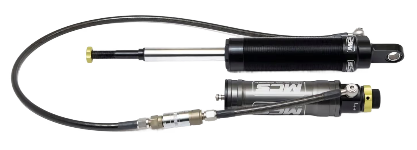

General information
- The dampers are charged with nitrogen gas. Front and rear dampers are factory charged to 12 bar (175 psi). Always set or check pressure with a proper shock inflation tool, with the shock fully extended and cooled off.
- Minimum pressure is 6 bar (85 psi). Maximum pressure is 18 bar (260 psi).
- If your dampers use a Quick Disconnect, release the pressure before opening the dry-break coupling. After installing the damper, reconnect the coupling and re-pressurize to 12 bar (175 psi).
- Do not use impact tools to install pin mount top nuts.
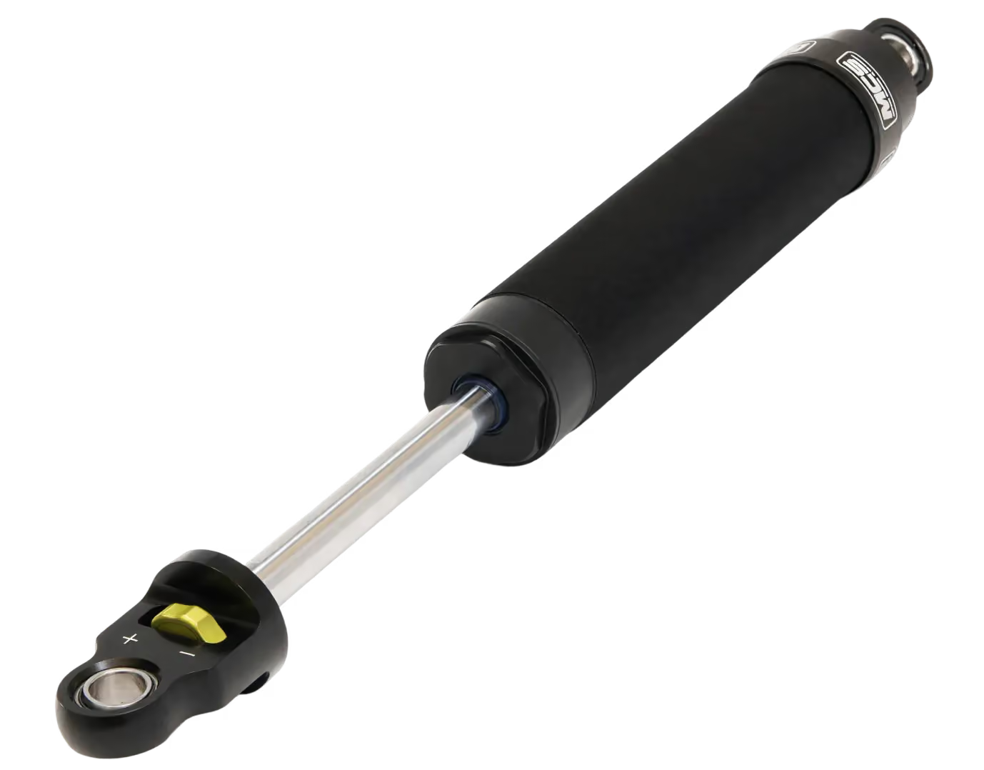
- The 8 mm brass hex nut at the top of the damper is the rebound adjuster. Do not use it to hold the shaft while installing the first top nut. Install the first top nut onto your mount and snug it with a wrench or socket, then cinch it with a quick jerking motion or a tap from a plastic hammer. This is more than enough to secure the shaft to the top mount. Install the second nut and tighten it against the first. Holding the first top nut with a tappet wrench (thin wrench) makes this easier.
- When fitting the rebound adjuster knob onto the 8 mm brass hex nut, make sure it clears all body components.
Adjustment instructions
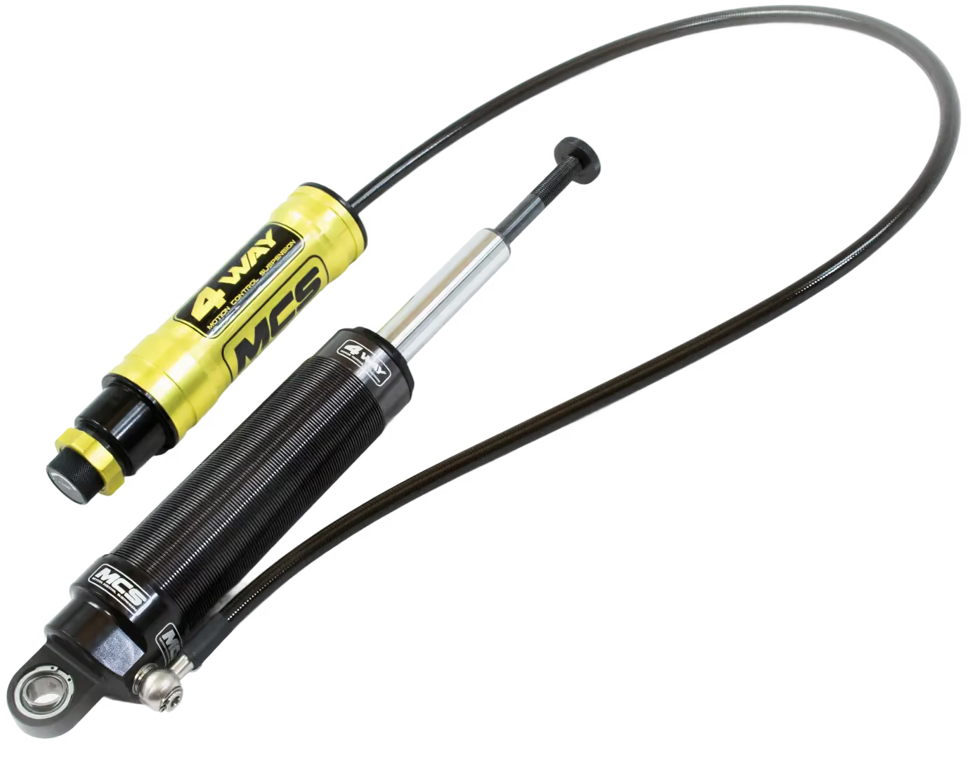
MCS 3-Way adjustable dampers are independently adjustable in rebound (extension) and in both low and high speed bump (compression).
Compression adjusters
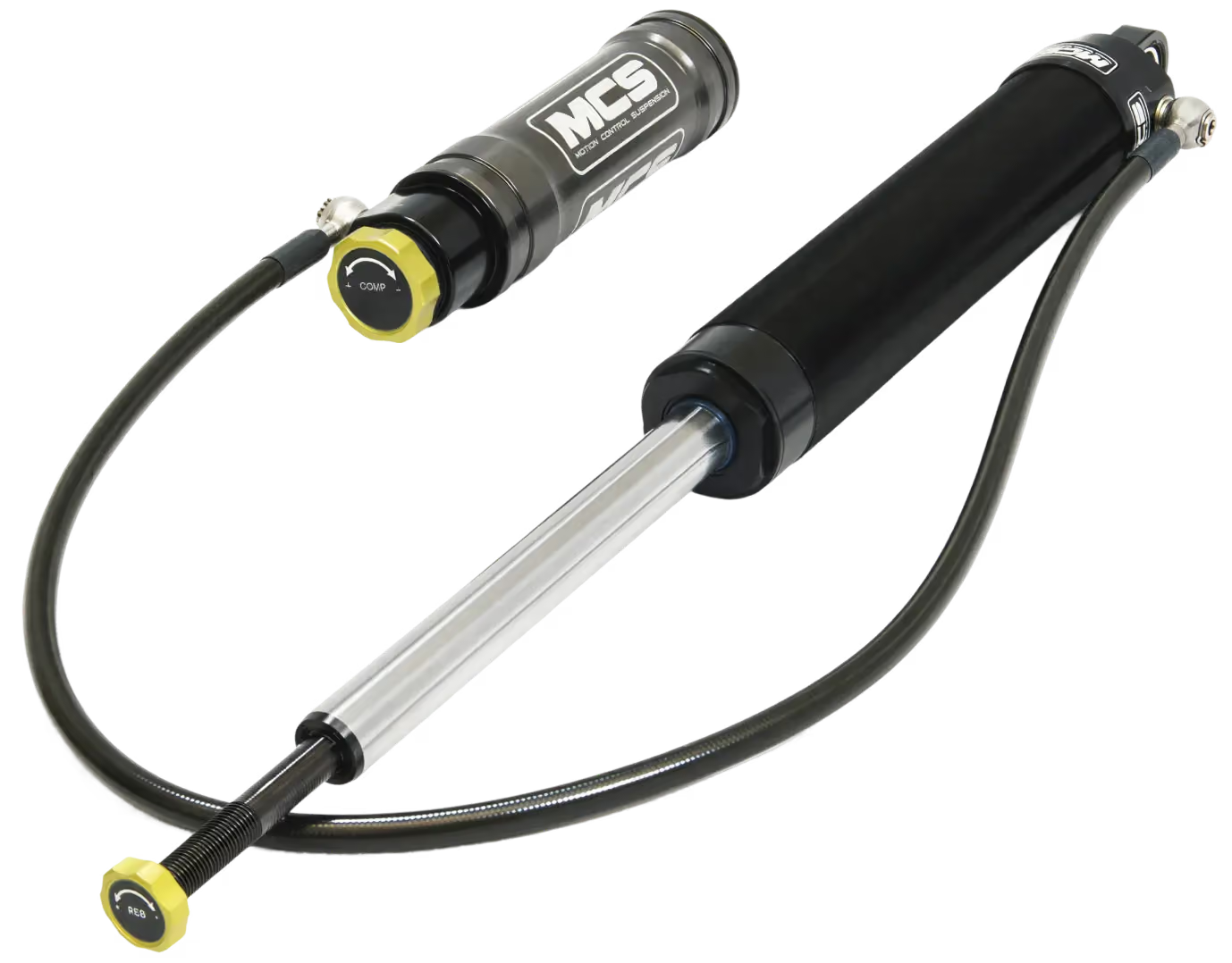
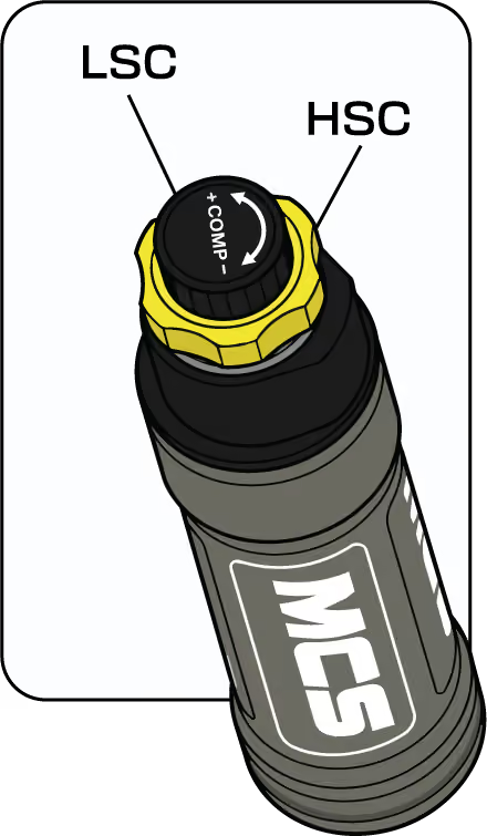
The Low Speed Compression (LSC) and High Speed Compression (HSC) adjusters are on top of the remote reservoir. The LSC is the small knob on top; the HSC is the large knob.
- LSC range: 10 positions (9 clicks). 0 = softest, 10 = stiffest.
- HSC range: 19 positions (18 clicks). 0 = softest, 18 = stiffest.
- Clockwise (−) softens compression damping.
- Counter-clockwise (+) stiffens compression damping.
When fitting the damper for the first time, set LSC to 5 clicks from 0 and HSC to 6 clicks from 0. Turn each knob clockwise until it stops, backing off slightly if needed so it settles into a detent. This is the “0” position. From here, turn the LSC knob counter-clockwise 5 clicks and the HSC knob counter-clockwise 6 clicks.
The LSC knob turns with the HSC knob relative to the canister body and stays indexed to it. This is correct and does not change the LSC setting, so you do not need to hold the LSC knob while turning the HSC knob.
Rebound adjustment
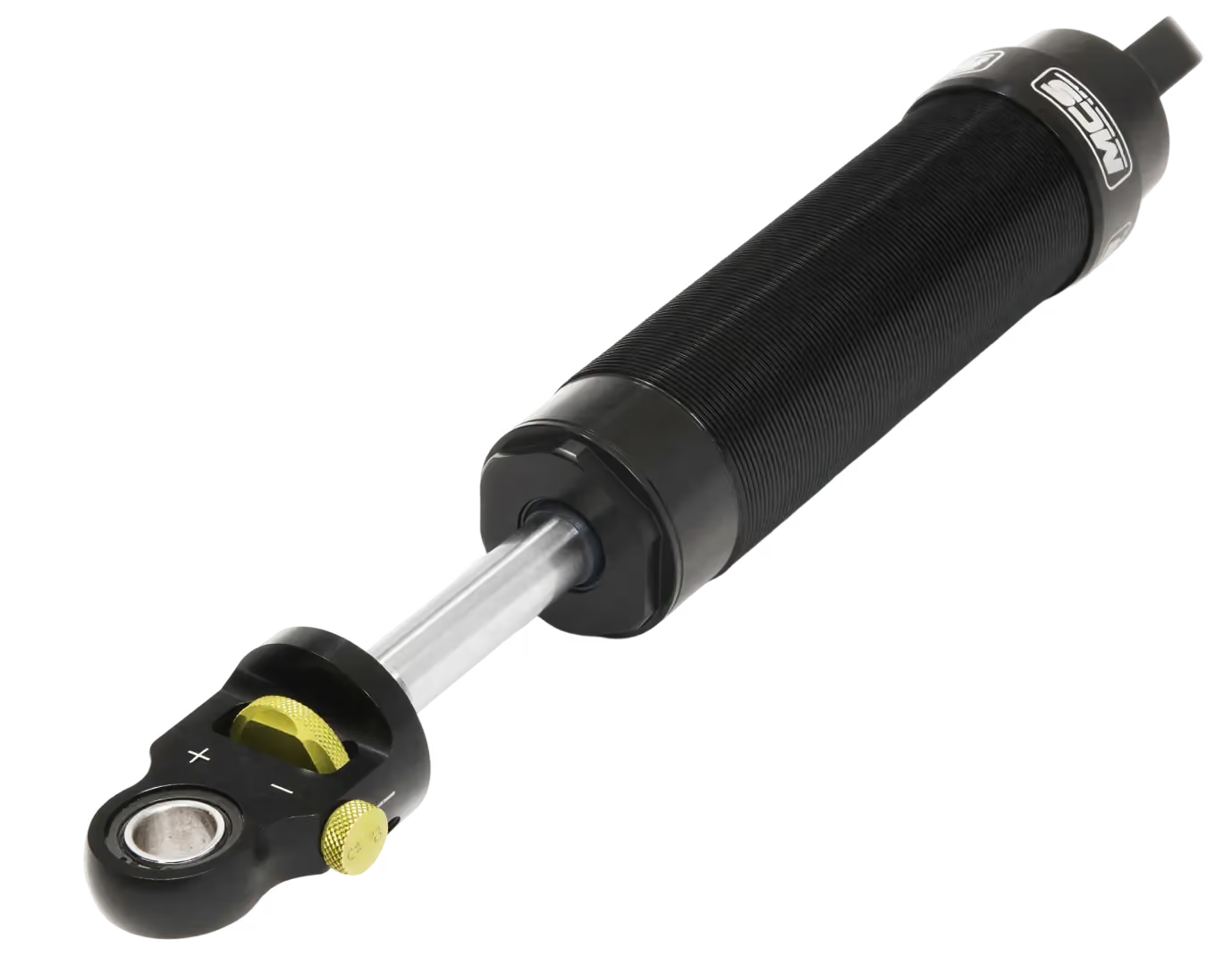
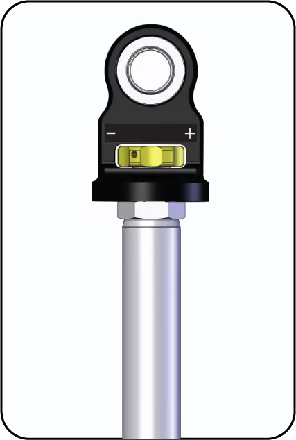
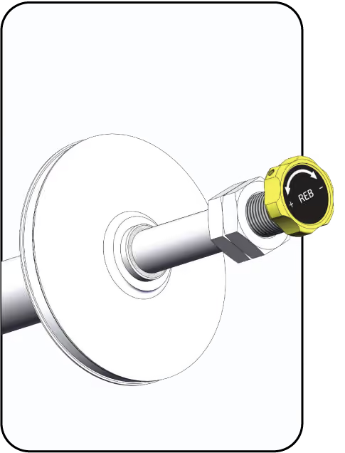
The rebound adjuster sits at the top of the piston rod. On strut and pin mount dampers it is the 8 mm brass hex nut: attach the separately supplied rebound adjuster knob to it after installation. Aluminum dampers with a top eye have the rebound adjuster wheel inside the top eye.
Range: 19 positions (18 clicks). 0 = softest, 18 = stiffest. Arrows on top of the knob show the firmer and softer directions.
- Clockwise (−) softens rebound (extension) damping.
- Counter-clockwise (+) stiffens rebound (extension) damping.
When fitting the damper for the first time, set rebound to 8 clicks from 0. Turn the knob clockwise until it stops, backing off slightly if needed so it settles into a detent.
Once it stops turning, DO NOT force it any further. This is the “0” position. From here, turn the knob counter-clockwise 8 clicks. Rebound is now set.
Need help?
Call us toll free on 866-391-1091 or on 770-220-7940, or email info@motioncontrolsuspension.com.