2WNR
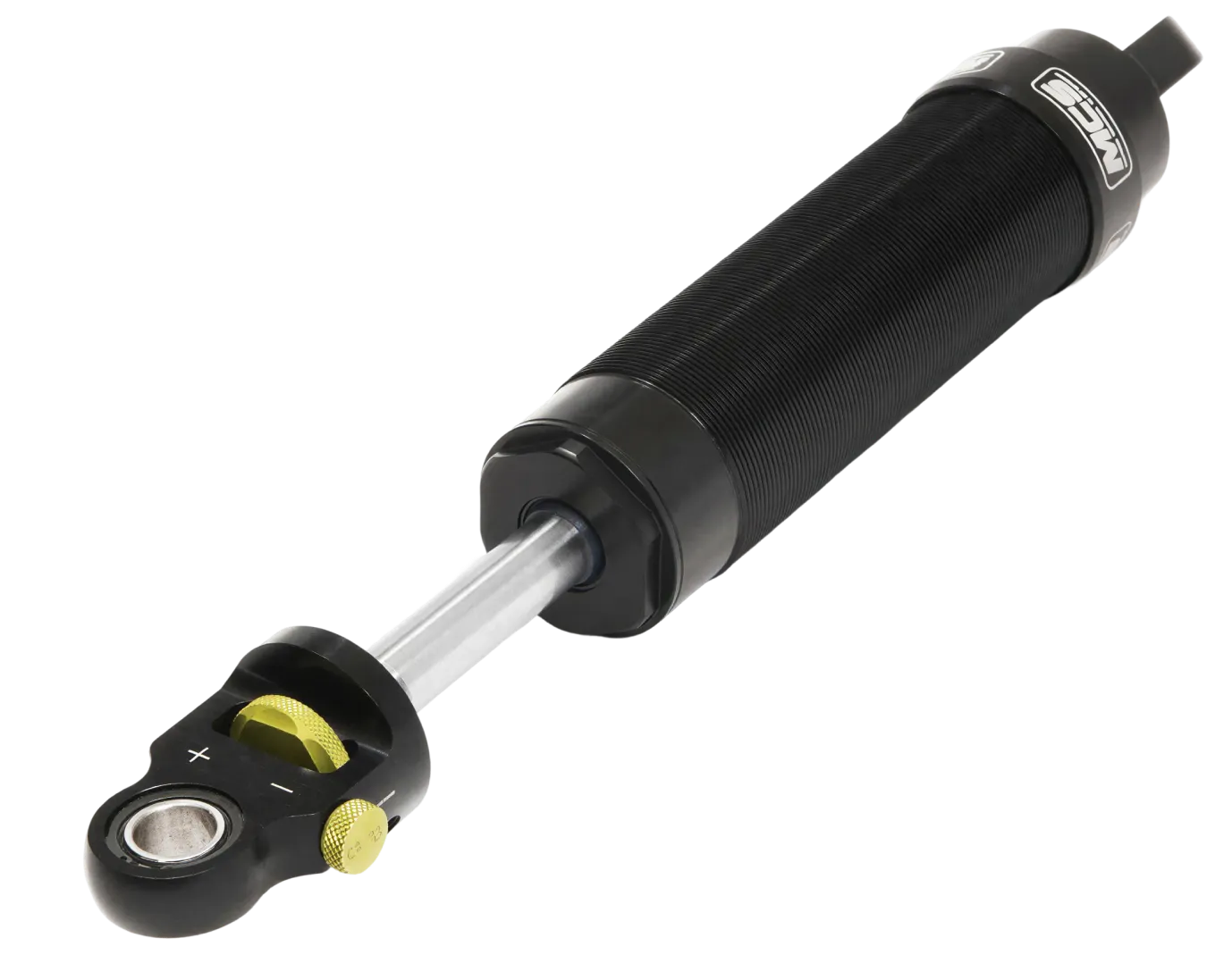
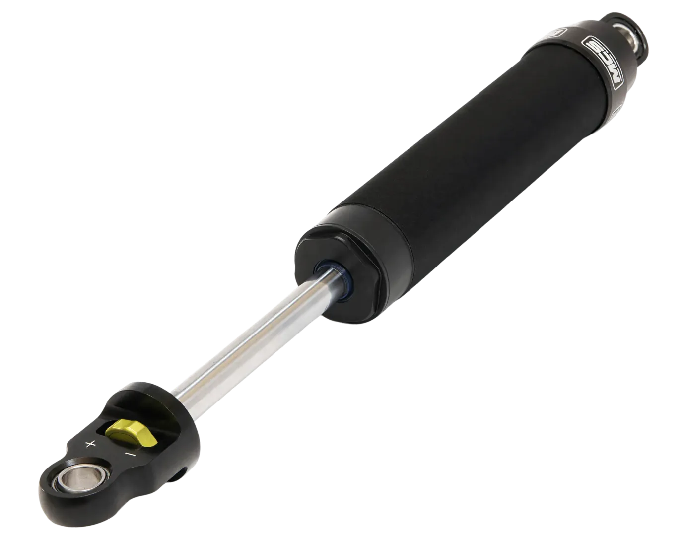
The MCS 2WNR is a double adjustable damper engineered for drivers who are ready to take control of both sides of the damper stroke without adding unnecessary complexity. Compression and rebound are independently adjustable through a single, easily accessible control, allowing fast, repeatable changes from under the hood or in the trunk.
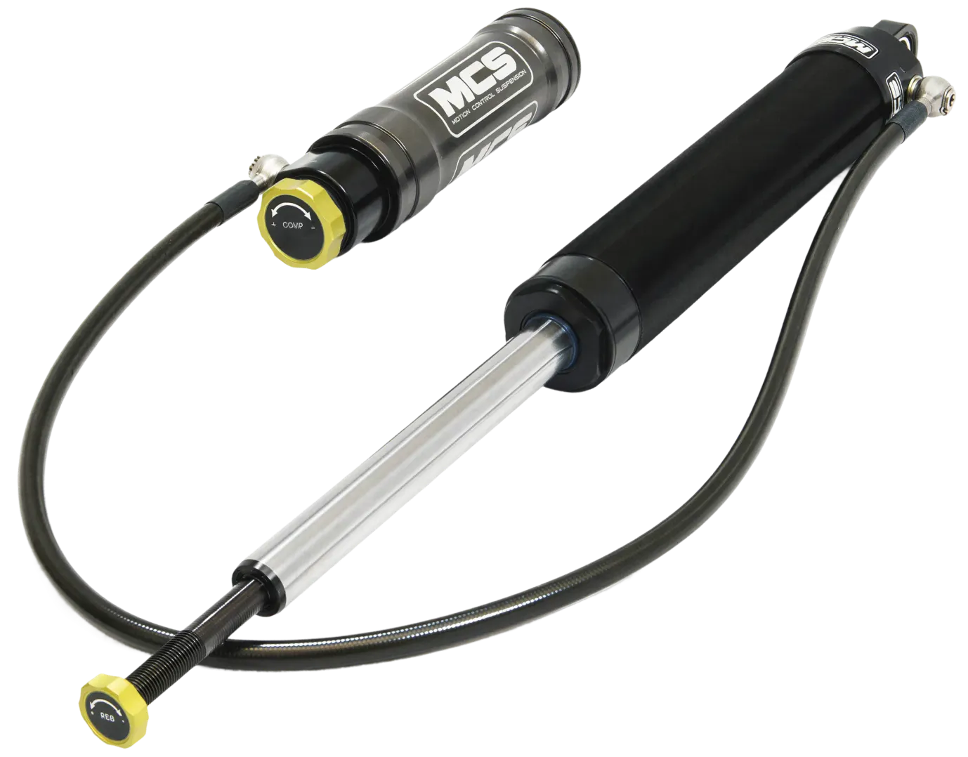
As driver confidence increases and setups become more deliberate, the 2WNR provides meaningful tuning range that continues to reward development rather than cap it. It bridges the gap between entry level adjustability and full remote reservoir systems, making it a long term solution as the car evolves from street duty to focused track use.
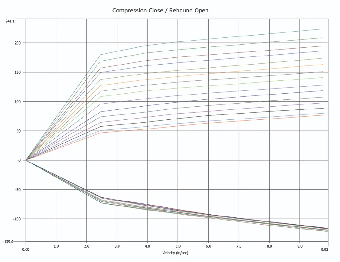
Damping forces are governed by blow off valves located directly on the main piston, delivering precise and consistent control across the adjustment range. This approach avoids the narrow effective window of needle valve systems and ensures each adjustment produces a measurable change in vehicle behavior.
Accessible. Precise. Built to grow with the car and the driver.
Technical Features
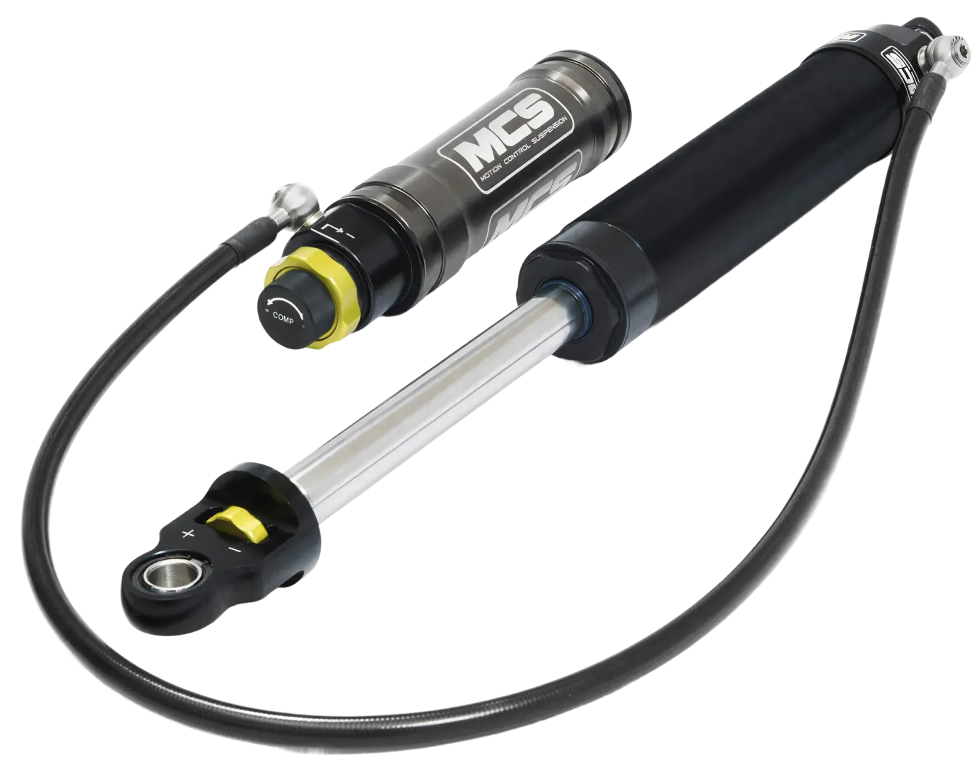
The MCS 2WNR uses a proprietary internal architecture that packages both compression and rebound control directly into the main piston, eliminating the need for external reservoirs. This design allows each circuit to be adjusted independently through a single, easily accessible control while maintaining precise separation between compression and rebound damping.
14 Clicks of Compression Adjustment
Compression damping on the 2WNR is adjusted with the control in the up position on pin style shaft ends, or in the C position on eyelet shaft ends equipped with the cam style adjuster. Each click delivers a clear, repeatable change.
With 14 usable clicks of compression adjustment, the driver can progressively increase platform support as grip, speed, and confidence grow. This enables finer control of weight transfer and more consistent tire contact without forcing the system into excessive stiffness.
Each adjustment produces a meaningful response, making compression tuning intuitive, effective, and easy to correlate to on track behavior.
18 Clicks of Rebound Adjustment
Rebound damping on the 2WNR is adjusted with the control in the down position on pin style shaft ends, or in the R position on eyelet shaft ends equipped with the cam style adjuster. Each click provides a clear, repeatable change.
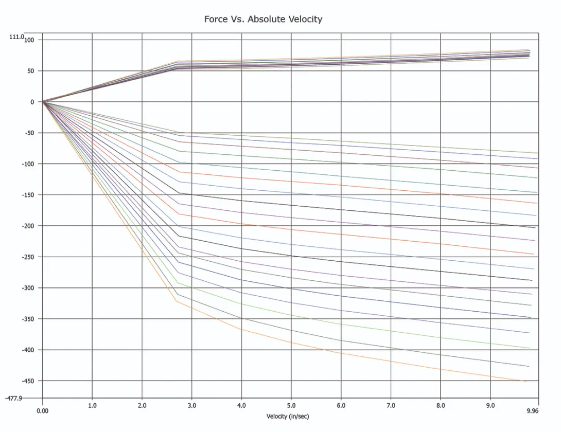
With 18 usable clicks of rebound adjustment, the driver can progressively increase spring control and fine tune chassis balance as pace and commitment increase. This allows precise control over how the car settles, transitions, and maintains grip without introducing instability.
Each adjustment delivers a meaningful response, making rebound tuning predictable and easy to translate into on track results.
<0.5%
Thousands of systems in service worldwide with less than a half percent reported failure rate. Built for reliability first, because confidence starts with consistency.
3.5x
Up to 3.5 times the service life of typical aftermarket coilover systems, delivering more miles, more track time, and fewer rebuild cycles.
0.3 sec
Per corner, per lap. Typical gain versus competing motorsport damper systems, measured in corner segments. Bigger gains when upgrading from entry level aftermarket suspension.
Technical Specifications
These specifications highlight the internal architecture, adjustment mechanisms, and core components that define damper performance, durability, and tuning range.

Shaft-End Adjustment with Positive Mechanical Detents, 14 Compression and 18 Rebound Positions
Precision CNC-Machined Components with Lot Control and Serialization
Nitrogen-charged internal reservoir with increased gas volume to support longer stroke, improved cavitation control, and consistent damping performance

Support Piston Provides Lateral Support at the Piston End of the Shaft Assembly
Shaft Guide Provides Lateral Support at the Upper End of the Damper Body
44 mm large-diameter main piston with a double digressive force curve and independent blow off valves on compression and rebound for controlled compliance without sacrificing support
Explore Other Products

Let’s Talk Solutions
See what makes Motion Control Suspension different. Whether you want to visit our facility, learn more about our process, or discuss a custom solution for your project, our team is here to listen and help.